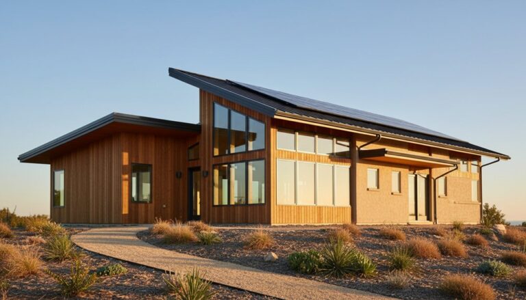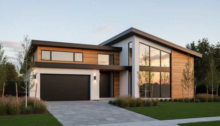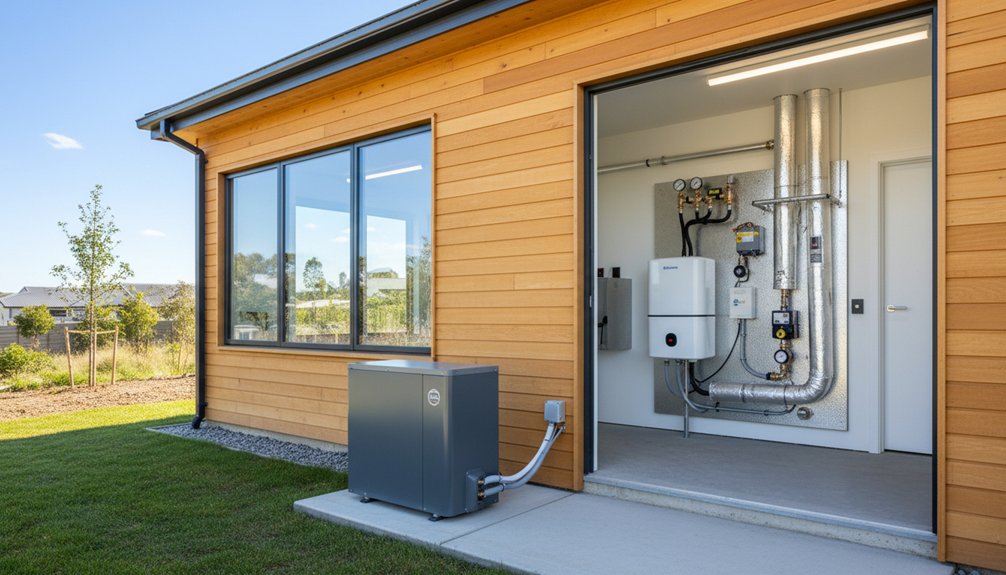
You’ll get a genuinely low‑energy new build with an advanced heat‑pump system by locking heat loss and emitter performance to verified data, not rules of thumb. Calculate loads with ACCA Manual J or EN 12831 using local design weather, then size the heat pump for capacity at 35–45 °C flow plus distribution losses. Hit airtightness via blower‑door testing (≤1.0 m³/(h·m²) @50 Pa) and use MVHR. Set weather compensation and long run times; next you’ll see how to commission and tune it.
Key Takeaways
- Calculate design heat loss using Manual J/EN 12831 with documented assumptions, then size the heat pump for design outdoor and flow temperatures.
- Prioritize a high-performance envelope: roof ≤0.11, walls ≤0.13, floors ≤0.10 W/m²K, windows Uw ≤0.9, and thermal bridges ψ ≤0.03 W/m·K.
- Achieve airtightness with blower-door verification (≤1.0 m³/(h·m²) @50 Pa or ≤0.6 ACH50) and sealed penetrations, tapes, and membranes.
- Use MVHR with low fan power and demand control to maintain IAQ independently of heating calls, reducing ventilation heat losses.
- Optimize heat-pump controls using weather compensation, smart zoning to prevent short-cycling, and commissioning/monitoring of flow, ΔT (5–7 K), and compressor starts.
Heat-Loss Calc and Heat-Pump Sizing Basics
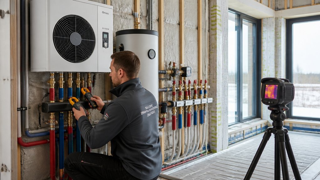
Before you pick a heat pump, you need a defensible design heat loss for the building, calculated to an accepted method (typically ACCA Manual J or EN 12831) using local winter design conditions, verified envelope U‑values, and controlled ventilation/infiltration assumptions.
You’ll enter geometry, orientation, glazing SHGC, and air-sealing targets, then document inputs and sources.
Don’t “oversize for safety”; size to design load plus distribution losses, then confirm manufacturer capacity at your design outdoor temperature and required supply-water temperature.
You’ll check emitter sizing (radiators, UFH) and target low ΔT to protect COP.
Account for thermal mass, which can buffer short cycling, but don’t credit it as steady-state loss reduction.
Validate summer comfort with solar shading assumptions separately.
Finally, run sensitivity on infiltration and setpoint for risk bounds.
Choose ASHP vs GSHP (and When Hybrids Work)

Once you’ve locked the design load and the lowest supply-water temperature your emitters can actually deliver, you can choose between an air‑source heat pump (ASHP), a ground‑source heat pump (GSHP), or a hybrid based on climate bin data, site constraints, and lifecycle cost—not brand folklore.
Use seasonal performance (SCOP/CSPF) and defrost penalties from your local bins: ASHPs usually win on capex and speed, but cold, humid climates increase compressor lift and reduce capacity.
Choose GSHP when you’ve got borefield/loop access and you need stable entering-water temperatures for predictable COP and quieter operation, supporting occupant comfort.
Specify hybrids only when bins show a small tail of extreme hours: let the heat pump cover 95–99% of annual load and stage a backup for peaks.
Plan Renewable integration with time-of-use control.
Fabric Targets for 35–45°C Flow Temperatures
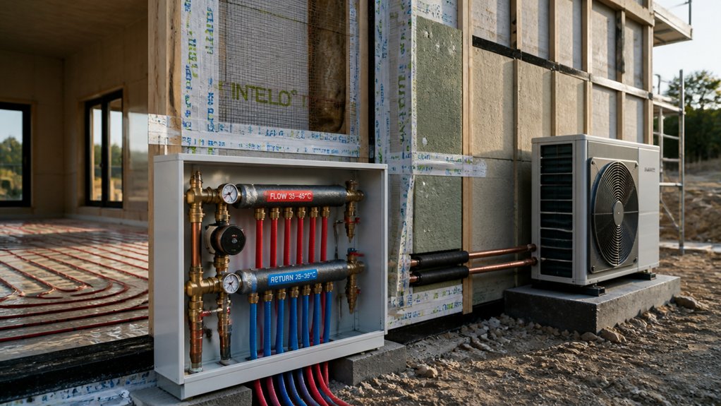
To hold 35–45 °C flow temperatures without oversizing your heat pump, you’ve got to drive your design heat loss down by tightening U‑values across walls, roof, floor, windows, and doors to meet your chosen standard.
You’ll also need verified airtightness (e.g., blower‑door result) so infiltration doesn’t dominate the load at design conditions.
Finally, you must control thermal bridging by setting ψ‑value targets and detailing junctions so the calculated heat loss aligns with as‑built performance.
Heat Loss And U‑Values
Because low flow temperatures (35–45 °C) leave you less “temperature headroom” at the emitters, the fabric has to do more of the work by driving the design heat loss down and stabilising internal surface temperatures.
Set U‑value targets that align with Part L/EN ISO 6946 calculations and your heat‑loss model: aim ≤0.11 W/m²K for roof, ≤0.13 for walls, ≤0.10 for floors, and windows (Uw) ≤0.9 with warm‑edge spacers.
Check junction ψ‑values in the heat‑loss worksheet but focus here on planar U‑values and glazing.
Limit summer gains with external solar shading sized from CIBSE TM59/TM52.
Keep indoor air quality stable by avoiding cold surfaces that drive downdraughts and occupant complaints.
Airtightness And Thermal Bridging
How tight does the envelope need to be when you’re designing for 35–45 °C flow temperatures? You’ll need infiltration low enough that ventilation is controlled, not accidental. Set a target ≤1.0 m³/(h·m²) @50 Pa (EN 12207/ISO 9972), and if you’re aiming near Passivhaus performance, drive toward ≤0.6 ACH50.
Commission with blower-door tests at first-fix and completion, and seal service penetrations with verified tapes, grommets, and liquid membranes to meet Airtightness standards.
Then treat junctions as heat-loss multipliers. Specify ψ-values via ISO 10211 modelling, cap linear thermal transmittance ≤0.01–0.03 W/m·K where feasible, and use continuous insulation, thermally broken fixings, and insulated cavity closers for Thermal bridging mitigation.
Set Airtightness and MVHR for Heat-Pump Homes
Where does a heat‑pump home gain or lose the most performance headroom—through the fabric or the air? You’ll usually reclaim it through controlled air: target ≤3.0 m³/(h·m²) @50 Pa (or ≤1.0 ACH50 for very low loads), verify with ISO 9972 blower‑door testing, and close leakage paths before services go in.
Tightening fabric cuts infiltration heat loss and prevents humidity spikes that drive defrost and lower seasonal COP.
You can’t rely on adventitious ventilation, so you’ll commission MVHR to meet EN 16798 and local regs: set 0.3–0.5 ACH nominal, balance supply/extract within 10%, and specify ≥85% heat‑recovery and low specific fan power.
Use CO₂/relative‑humidity demand control to protect Indoor air quality, document filters and commissioning, and keep Renewable incentives eligibility.
Heat-Pump Emitters: UFH vs Oversized Radiators
Airtightness and correctly commissioned MVHR lock down your ventilation losses; the next performance lever is emitter temperature, since a heat pump’s seasonal COP tracks the leaving‑water temperature (LWT) you ask for.
For a Heat emitter comparison, design to BS EN 12831 room loads, then pick emitters that meet output at ≤35–45°C LWT.
UFH typically runs 30–35°C with 5–10 K ΔT, giving stable mean radiant temperatures and allowing weather compensation to stay low.
Oversized radiators can match this if your Radiator sizing uses EN 442 outputs corrected for lower ΔT (e.g., 50/40/20 becomes 35/30/20), often requiring 2–3× panel area.
Keep flow rates and ΔT aligned to the manufacturer’s limits and your hydraulic design.
Heat-Pump Hot Water: Cylinders, Buffers, Volumes
A well-designed hot‑water arrangement stops your heat pump short‑cycling and keeps DHW recovery efficient by matching stored volume and coil performance to your building’s load profile.
Size your DHW cylinder from daily litres and peak draw, then verify coil rating at design flow temperature (e.g., 45–50°C) so reheat meets demand without high lift.
For most low‑energy homes, 180–250 L suits 2–4 occupants; validate with EN 16147/ErP load profiles.
Use a buffer only when minimum system water volume can’t meet the heat pump’s minimum run time; otherwise keep hydraulic volume in the emitters.
Target total volume so ΔT and flow prevent cycling.
Enable solar integration via a lower solar coil and stratification baffle.
Coordinate ventilation strategies to limit humidity-driven DHW spikes.
Controls That Keep Heat Pumps Efficient (Zoning, WC)
To keep your heat pump in its high-COP operating band, you’ll control demand with smart zoning that limits short-cycling and maintains stable emitter flow temperatures.
You’ll design zones around heat-loss profiles and occupancy, then validate performance with run-time, ΔT, and compressor start counts.
You’ll add weather compensation so the controller resets flow temperature to outdoor conditions, meeting comfort targets with the lowest possible lift and seasonal energy use.
Smart Zoning Strategies
When you zone a low‑energy new build, the controls have to protect heat‑pump efficiency by keeping run times long, flow rates stable, and leaving at least one zone with enough load to absorb minimum output. You’ll set zoning around true load diversity, not room count: group similar heat‑loss rates, emitter types, and schedules, then size actuators and manifolds to maintain design ΔT and minimum circuit flow.
Smart thermostats should run wide proportional bands and longer cycle times, acting as demand limiters rather than on/off switches. Use zoning algorithms that enforce minimum open‑zone area, stage setpoint changes, and coordinate with buffer or low‑loss header logic to prevent short cycling.
Commission with measured flow, return temperatures, and COP trends.
Weather Compensation Controls
Because outdoor temperature drives the bulk of space‑heating load, weather compensation (WC) should command your heat pump’s leaving‑water temperature via a heating curve, not via room thermostats calling for maximum flow temperature.
You’ll set slope and offset from your design heat loss and emitter output, then commission to hold stable room temperature with low ΔT and long runtimes. Use room stats only as high‑limit trims per zone to prevent overshoot, not to force cycling.
Log flow, return, and outdoor temps; adjust the curve until compressor starts per hour stay low and COP rises. Coordinate WC with solar shading so passive gains don’t spike demand.
Maintain indoor air quality by keeping ventilation rates independent of space‑heating calls. Validate under EN 14825 seasonal conditions.
Commissioning Checks: Flow Rates, ΔT, Settings, Handover
Although the design spec may look complete on paper, you only lock in seasonal performance once you commission the system against measured flow rates, ΔT, control settings, and a documented handover pack.
Start by verifying pump duty points with calibrated flow meters, then balance each circuit so design L/s matches as-built.
Record heat-pump ΔT at steady load; you’ll typically target 5–7 K on emitters and confirm minimum flow to avoid lockouts.
Validate weather-comp curves, DHW setpoints, and anti-legionella cycles against commissioning sheets and local standards.
Prove interlocks with ventilation to protect indoor air quality and prevent simultaneous heat/cool conflicts.
Finally, issue a handover pack: as-fitted schematics, parameter list, test data, maintenance plan, and evidence for renewable incentives audits.
Frequently Asked Questions
What Grants or Incentives Are Available for Heat-Pump New Builds in My Area?
You can access Government rebates and Tax incentives for heat‑pump new builds, but eligibility depends on your country, state/province, and utility service territory. Check your utility’s DSM/efficiency portal, then search national and local databases (e.g., DSIRE in the US) for programs tied to AHRI‑rated equipment, minimum HSPF2/SEER2, and permit sign‑off.
Confirm stackability, income caps, and required commissioning documentation before you apply.
How Long Does a Heat-Pump System Typically Last, and What Warranties Apply?
Often, just as you plan maintenance, your system’s clock aligns: Heat pump lifespan typically runs 15–20 years (air-source) and 20–25+ years (ground-source) under commissioning and annual service to manufacturer specs.
You’ll usually get 5–10 years parts, 1–5 years labor, and 10+ years compressor coverage; some brands extend with registration.
Read Warranty coverage exclusions for refrigerant leaks, water quality, and improper airflow.
What Maintenance Tasks and Servicing Costs Should I Expect Each Year?
Expect annual filter cleaning/replacement (monthly checks), coil and condensate drain inspection, refrigerant leak/charge verification, airflow/static-pressure tests, and controls/defrost checks to protect System efficiency.
Schedule a professional service visit yearly: £150–£300/$150–$400, plus filters (£10–£50).
Every 2–5 years, expect deeper cleaning and calibration: add £100–£250.
Cost comparisons: heat pumps often match/undercut boiler servicing, but repairs cost more if components fail.
How Noisy Are Outdoor Units, and What Planning Rules Cover Noise Limits?
Outdoor noise levels for modern outdoor units typically run 45–60 dB(A) at 1 m, dropping ~6 dB per distance doubling. You’ll hear a low fan/compressor hum, louder in defrost.
You should check Planning noise regulations: UK permitted development usually requires MCS 020, with ≤42 dB(A) at the nearest neighbour boundary/“relevant point” under worst‑case operation.
If you exceed it, you’ll need planning or mitigation (screening, relocation).
Can a Heat Pump Be Integrated With Solar PV, Batteries, or Smart Tariffs?
Why not make your heat pump work smarter with solar PV? Yes—you can integrate it with PV, batteries, and smart tariffs using inverter signals, CT clamps, and API-enabled controllers for system integration.
You’ll raise Heat pump efficiency by shifting runtime to high-COP periods and surplus PV.
You’ll charge batteries when tariffs dip, then run the compressor during peaks.
You’ll validate performance via MCS guidance, metered COP, and time-of-use logs.
Conclusion
You’ve chased low flow temperatures, nailed heat‑loss calcs, and sized the heat pump to design load—not optimism. You’ve picked ASHP/GSHP on COP, set fabric to hold 35–45 °C, hit airtightness targets, and balanced MVHR. You’ve chosen emitters for ΔT, sized cylinders/buffers by litres and recovery, and kept controls simple so weather compensation can actually work. Ironically, the “advanced” system only performs when you commission it ruthlessly—and then leave it alone.
About the Author